

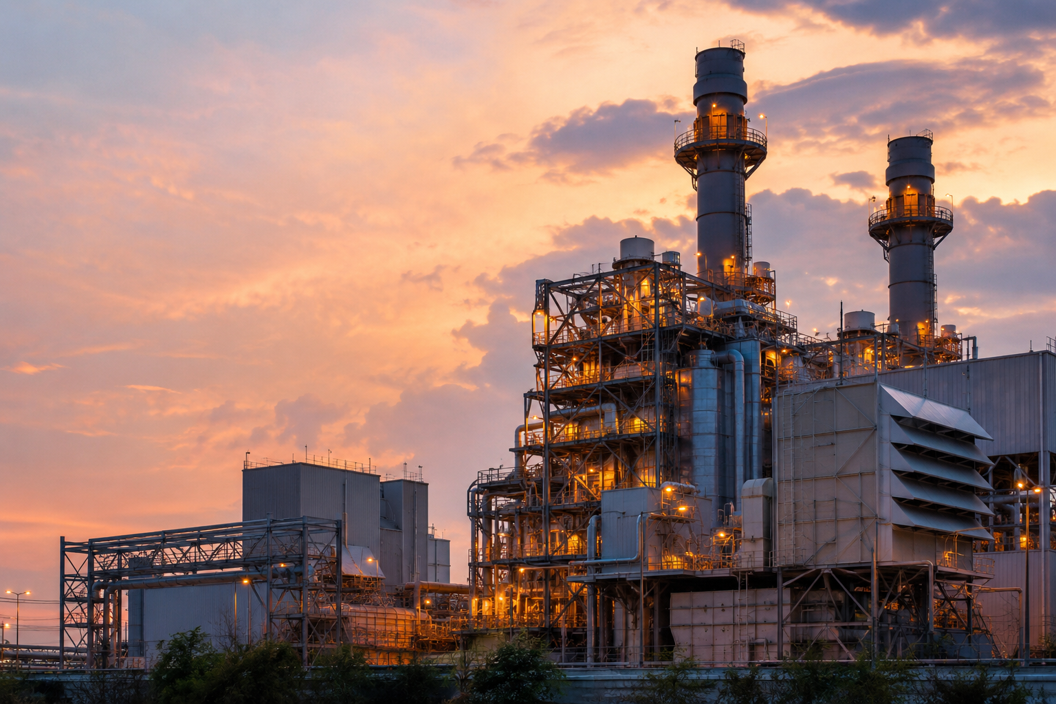
A boiler is a pressure system that transfers heat into treated water to produce steam. The basic idea sounds simple, but a large power plant boiler is one of the most complicated systems in heavy industry.
A utility boiler does not merely “boil water.” It must continuously deliver steam at a controlled:
That steam drives a turbine-generator to produce electricity. A package boiler usually performs the same basic heat-transfer job on a smaller, factory-assembled scale, supplying steam for refinery processes, plant heating, startup systems, cleaning, tracing, deaeration, and other industrial uses.
In a conventional steam power plant, the boiler converts fuel energy into high-pressure, high-temperature steam.
The overall cycle is:
Fuel and air → boiler → superheated steam → turbine → generator → condenser → feedwater system → boiler
The steam expands through the turbine and turns the turbine shaft. The turbine drives the generator, which produces electricity. After leaving the turbine, the steam is condensed back into water, pumped to a higher pressure, heated through feedwater heaters, and returned to the boiler.
This closed-loop process is known as the steam or Rankine cycle.
The boiler is therefore the heat source for the entire steam cycle. The turbine converts steam energy into rotation, but the boiler puts that energy into the steam in the first place.
A boiler has two systems operating at the same time.
Condenser → condensate pumps → feedwater heaters → deaerator → boiler feed pumps → economizer → steam drum or separator → waterwalls → superheater → turbine
Fuel preparation → burners → furnace → superheater and reheater sections → economizer → air heater → emissions equipment → induced-draft fan → stack
The tube walls keep these two systems separated. Water and steam remain inside the pressure parts while fire and combustion gases remain outside them.
A tube failure breaks that separation. High-pressure water or steam can then discharge into the furnace, forcing a shutdown and potentially creating severe personnel and equipment hazards.
Water entering a power boiler cannot be ordinary untreated water.
Raw water may contain:
These contaminants can cause scale, corrosion, carryover, and turbine deposits.
After steam leaves the turbine, it enters the condenser. Cooling water removes the remaining heat and turns the steam back into condensate.
Condensate is valuable because it is already hot and has usually been highly purified. It is collected and pumped back through the cycle instead of being discarded. DOE guidance notes that returned hot condensate reduces the amount of energy required to produce steam again.
Feedwater heaters use steam extracted from different turbine stages to warm the condensate before it reaches the boiler.
Preheating the water:
The deaerator heats the water and removes dissolved oxygen and other noncondensable gases.
Oxygen is extremely damaging in a boiler system. It can cause deep localized pitting in economizers, feedwater piping, drums, and tubes.
The deaerator also acts as a storage point for boiler feedwater and gives the boiler feed pumps a dependable supply of hot water.
The boiler feed pumps raise feedwater pressure above boiler operating pressure.
Without that pressure increase, water could not enter the boiler. Large utility feed pumps may consume substantial power because they must move large volumes of water against extremely high boiler pressure.
The DOE steam sourcebook describes the feed pumps as increasing feedwater pressure above boiler pressure to complete the cycle.
The economizer is normally the first major boiler pressure part that receives feedwater.
It is located in the cooler end of the flue-gas path. Hot combustion gas leaving the hotter boiler sections passes across economizer tubes and preheats the incoming feedwater.
The economizer recovers energy that would otherwise leave through the stack. It also reduces the temperature difference between the incoming feedwater and the boiler’s evaporating circuits.
Babcock & Wilcox notes that economizers improve boiler efficiency and help reduce thermal shock and feedwater-temperature fluctuations.
Economizer tubes do not normally produce the final superheated steam. Their main job is to raise feedwater temperature before it enters the drum or once-through boiler circuits.
Many subcritical power boilers use a steam drum.
The steam drum is a large pressure vessel located near the top of the boiler. It performs several important functions:
The drum contains separators, cyclones, baffles, scrubbers, and dryers that remove water droplets from the steam.
Poor separation can send moisture and boiler-water contaminants into the superheater and turbine. Excessive drum-water solids, foaming, or spray can produce steam carryover and high steam impurity levels.
Downcomers carry relatively dense water from the steam drum toward the lower furnace headers.
Many downcomers are located outside the highest furnace heat because their job is to deliver water, not produce steam.
Lower headers distribute water into the furnace wall tubes.
A header receives flow through one or more large pipes and distributes it into many smaller tubes. At the upper end, another header collects the steam-water mixture and returns it toward the drum.
Waterwall tubes form the furnace enclosure.
Modern waterwalls are commonly welded together with steel membrane bars, creating a gas-tight wall.
The tubes simultaneously:
As water moves through the heated tubes, part of it becomes steam. The resulting steam-water mixture returns to the drum, where the steam and water are separated.
The water flowing inside the tube cools the metal. This is why maintaining proper circulation is critical. A tube exposed to furnace heat without sufficient internal flow can overheat very quickly.
In a natural-circulation boiler, circulation is created by the density difference between the cooler water in the downcomers and the lighter steam-water mixture in the heated riser tubes.
The heavier water moves downward while the lighter mixture rises.
Some boiler designs use circulation pumps to assist or create the circulation. These are called controlled- or forced-circulation systems.
Poor circulation can result from:
Circulation problems can create localized overheating even while average boiler conditions appear normal.
Steam leaving the drum is normally saturated steam. It is at the boiling temperature corresponding to the drum pressure, but it is not yet hot enough for efficient turbine operation.
The superheater raises the steam temperature above saturation without significantly increasing its pressure.
Superheaters are tube banks located in hotter portions of the boiler. They may include:
The final superheater outlet connects to the main steam piping and then to the high-pressure turbine.
Superheated steam improves turbine performance and reduces the chance of moisture forming during the early stages of expansion.
Unlike waterwalls, superheater tubes are cooled by steam rather than boiling water. Steam has a lower ability to remove heat from the tube wall, making superheater metal temperature especially important.
After steam expands through the high-pressure turbine, its pressure and temperature have dropped.
In a reheat power plant, the steam returns to the boiler and passes through the reheater. It is heated again and then sent to the intermediate-pressure turbine.
The path is:
Final superheater → high-pressure turbine → cold reheat piping → reheater → hot reheat piping → intermediate-pressure turbine
Reheating:
The reheater resembles a superheater, but the steam entering it has already passed through part of the turbine.
An attemperator, also called a desuperheater, controls steam temperature by spraying carefully controlled feedwater into the steam.
Attemperation may be used between superheater stages or reheater stages.
The spray water must be extremely clean. Contaminated spray water can deposit solids inside superheater tubing, main steam piping, or the turbine.
Too much spray can:
Too little spray allows steam temperature to rise above the allowable limit.
A conventional subcritical drum boiler separates water and steam in a steam drum.
A supercritical boiler normally uses a once-through design. Feedwater passes through the economizer, furnace walls, and heating surfaces without continually recirculating through a large steam drum during normal operation.
The fluid transitions into steam as it passes through the boiler circuit and then enters the superheater. B&W describes its supercritical designs as once-through boilers using water-cooled furnaces, superheaters, reheaters, economizers, and air heaters.
Once-through boilers require extremely precise control of:
Because there is less stored water inventory, changes in firing and feed flow can affect outlet conditions quickly.
Power boilers can burn:
Each fuel requires a different preparation, burner, and ash-handling system.
In a pulverized-coal plant, coal moves from storage through conveyors and feeders into pulverizers.
The pulverizers:
Primary air carries the pulverized coal to the furnace. Secondary air enters through the windbox and burner registers to complete combustion.
Coal firing also requires systems for bottom ash, fly ash, pyrites, and accumulated deposits.
Natural-gas and fuel-oil systems are generally simpler than pulverized-coal systems, but they still require:
The burner must hold the flame away from the waterwall and distribute heat evenly through the furnace.
The forced-draft fan pushes combustion air toward the boiler.
The air normally passes through an air heater before entering the windbox. Heating the combustion air improves ignition and reduces the amount of fuel energy required to bring the incoming air up to furnace temperature.
On many coal boilers, the primary-air fan supplies air to the pulverizers and transports pulverized coal to the burners.
The induced-draft fan pulls flue gas through the boiler, emissions equipment, and stack.
The FD and ID systems work together to keep the furnace slightly below atmospheric pressure.
A negative furnace pressure helps keep flame and hot gases from escaping through observation doors, penetrations, and casing leaks.
Fans, burners, pulverizers, air heaters, drums, headers, tube banks, and pressure parts are all critical elements considered during boiler condition assessments.
After combustion occurs, hot gas moves through the boiler in a controlled path.
A typical path is:
Furnace → superheater → reheater → generating or convection banks → economizer → air heater → emissions controls → ID fan → stack
The hottest gas first transfers heat to furnace waterwalls and high-temperature steam surfaces.
As the gas cools, it passes across lower-temperature surfaces such as the economizer and air heater. The goal is to recover as much usable heat as possible without cooling the flue gas enough to cause acid condensation, corrosion, or emissions-equipment problems.
Coal, biomass, waste, and some oil fuels leave ash and deposits on boiler surfaces.
Deposits insulate the tubes and interfere with heat transfer. They can also redirect flue gas, produce localized erosion, and increase pressure drop.
Sootblowers use steam, air, or sometimes water to clean tube surfaces.
Common types include:
A sootblower must be powerful enough to remove deposits without cutting or eroding the tubes.
B&W describes sootblowers as automated devices that use steam, compressed air, or high-pressure water to remove ash from heat-transfer surfaces.
Large fossil-fired boilers may have several pollution-control systems downstream.
SCR systems reduce nitrogen oxides by injecting ammonia or urea and passing the gas through a catalyst.
An ESP electrically charges fly-ash particles and collects them on plates. EPA describes an ESP as using electrical energy to charge and remove particles from a gas stream.
A fabric filter or baghouse passes the gas through filter bags that capture particulate matter.
Wet or dry scrubbers remove sulfur dioxide from flue gas.
A large coal boiler’s complete gas path can include an SCR, particulate collection, sulfur-dioxide removal, and sorbent systems before the cleaned gas reaches the stack.
Boiler tubing is not made from one material throughout the unit.
Material selection depends on:
Waterwalls often use carbon steel or low-alloy steel because the boiling water inside keeps tube-metal temperature relatively controlled.
However, waterwalls in waste-to-energy, biomass, and corrosive coal service may require stainless weld overlay, nickel-alloy overlay, or specialized coatings because of severe fireside corrosion.
Economizers commonly operate at lower metal temperatures, so carbon or low-alloy steels may be suitable.
Their common threats include:
Superheater and reheater tubes operate at significantly higher metal temperatures. They may require chrome-moly, creep-strength-enhanced ferritic steels, austenitic stainless steels, or advanced nickel-containing alloys.
Examples found in high-temperature boiler service include material families such as:
These alloys are selected primarily for creep strength, steam oxidation resistance, and fireside corrosion resistance, not simply because they transfer heat better.
Advanced superheater materials are specifically developed to resist high-temperature creep and oxidation.
High-temperature outlet headers and main steam piping can use thick-wall creep-resistant alloys such as P91 or P92, depending on design conditions.
These materials require strict control over:
The chemistry and heat treatment create the microstructure that gives these materials their strength. Incorrect welding or heat treatment can damage that structure even when the weld looks acceptable from the outside.
Short-term overheating occurs when metal temperature rises high enough that the tube can no longer contain pressure.
Possible causes include:
The failed tube may show a wide-open, thin-edged rupture.
Creep is slow, permanent deformation caused by stress at elevated temperature.
A tube may gradually swell, lose strength, and eventually rupture after thousands of operating hours.
Superheaters and reheaters are especially vulnerable. B&W identifies long-term overheating and creep as common life-limiting mechanisms in alloy superheater and reheater tubes.
Scale and deposits insulate the metal from the cooling water.
The tube wall then runs hotter even though the water or steam outlet temperature may appear normal.
Under certain conditions, corrosion reactions can produce atomic hydrogen that enters the steel and reacts with carbides.
This can weaken the steel internally and lead to brittle failures.
Repeated temperature, pressure, and mechanical cycling can initiate and grow cracks.
Areas around attachments, membrane welds, penetrations, and rigid restraints are especially sensitive to differential expansion.
Fuel contaminants can create aggressive deposits on the outside of waterwalls, superheaters, and reheaters.
Waste, biomass, and some coal fuels may contain combinations of chlorine, sulfur, sodium, potassium, vanadium, or other compounds that accelerate corrosion.
Fly ash, sootblowers, and high-velocity gas can gradually remove tube metal.
Leading edges, bends, and areas where gas flow changes direction often suffer the greatest wear.
Boiler-tube failure remains a major cause of forced outages, which is why utilities use thickness testing, visual inspection, oxide measurements, metallurgical sampling, and remaining-life assessments.
A large boiler is controlled as an integrated system.
Drum level must be maintained within a narrow range.
Too low can uncover tubes and interrupt circulation. Too high can send water into the superheater.
Large drum boilers commonly use three-element control based on:
Steam bubbles can make the indicated level temporarily rise or fall during load changes. This is known as swell and shrink, and it is one reason drum-level control is more complicated than controlling an ordinary water tank.
The boiler master coordinates fuel and air with steam demand.
Cross-limiting logic helps prevent a fuel-rich condition:
Draft control adjusts ID fan, FD fan, dampers, or fan vanes to maintain the desired furnace pressure.
Superheat and reheat temperatures may be controlled through:
The burner-management system controls purge, ignition, flame proving, and fuel isolation.
Trips may occur for conditions such as:
Power boilers are generally constructed under ASME Boiler and Pressure Vessel Code Section I rules governing the pressure integrity of power boilers.
A package boiler is a boiler that is substantially assembled at the manufacturer before being shipped to the site.
The term package describes the method of construction and delivery. It does not automatically mean firetube, low pressure, or small.
Package boilers can be:
The boiler, burner, controls, and much of the trim are engineered as an integrated unit.
Industrial package boilers may arrive in one major piece, several shop-assembled modules, or with the steam drum shipped separately because of transportation limits.
A firetube boiler contains a large shell filled with water.
Hot combustion gas flows through tubes passing through that water.
The arrangement is:
Fire and flue gas inside the tubes → water outside the tubes
A burner fires into a furnace tube. The hot gas travels through one or more passes before exiting to the stack.
A three-pass firetube design may route the gas:
Firetube boilers are common where the facility needs dependable saturated steam at moderate capacities and pressures.
Typical uses include:
Firetube package boilers are compact and carry a relatively large water inventory.
The large water mass helps stabilize steam pressure, but it also means the unit stores significant thermal energy and can respond more slowly to rapid load changes.
EPA describes firetube boilers as units where hot combustion gases flow through tubes while the water being heated surrounds the tubes.
In a watertube package boiler, water and steam flow inside the tubes while combustion gas flows around the outside.
The arrangement is:
Water and steam inside the tubes → fire and flue gas outside the tubes
A package watertube boiler may include:
Watertube construction is better suited for higher steam pressures, larger steam flows, and quicker load response.
The smaller tube diameter allows the pressure parts to withstand higher pressure without requiring one enormous water-filled shell.
Package watertube boilers are widely used in:
EPA guidance distinguishes watertube boilers as systems where water circulates through tubes heated externally by the furnace and flue gas.
A typical package boiler system works as follows:
Makeup water passes through some combination of:
The exact treatment depends on pressure, steam purity requirements, and condensate-return quality.
The feedwater pump raises the water above boiler pressure and pushes it into the boiler.
A check valve prevents boiler water from flowing backward toward the feed system.
The burner mixes fuel with combustion air.
A forced-draft fan may supply the air. The burner-management system proves that the furnace has been purged, lights the pilot, proves pilot flame, opens the main fuel valves, and verifies main flame.
In a firetube boiler, hot gas flows through tubes surrounded by water.
In a watertube boiler, water flows inside tubes exposed to the furnace and hot flue gas.
Steam rises into the upper portion of a firetube shell or enters the steam drum of a watertube boiler.
Separators and adequate steam space help prevent water droplets from entering the steam header.
The steam passes through the nonreturn valve and main steam stop valve into the plant steam system.
As steam demand changes, the burner increases or decreases firing.
Depending on the system, firing may be:
Fully modulating burners continuously adjust fuel and air to match the steam load and reduce excessive cycling.
A working package-boiler installation is more than the boiler vessel.
It may require:
Package systems can also be supplied on skids with feed systems, water treatment, and blowdown equipment as part of a more complete steam solution.
As steam leaves the boiler, most dissolved solids remain behind in the boiler water.
Without blowdown, the concentration continues to rise.
Continuous blowdown removes a controlled amount of water from an area where dissolved solids are concentrated.
Bottom blowdown removes settled sludge from low points in the boiler.
Too little blowdown can cause:
Too much blowdown wastes:
Blowdown heat can be recovered through a flash tank or heat exchanger.
Low water is one of the most dangerous package-boiler conditions.
If heat-transfer surfaces are exposed while the burner continues firing, the metal can overheat and lose strength.
Package boilers generally use independent low-water cutoffs. Depending on the installation, one may stop firing and another may lock the boiler out.
Water must never be immediately added to a severely overheated, dry boiler unless the correct emergency procedure has been established. Rapid introduction of water onto overheated metal can cause violent steam generation and catastrophic damage.
Before ignition, the boiler must be purged with air to remove any combustible mixture that may be inside the furnace or gas passes.
The basic sequence is:
Prove airflow → open dampers → purge for required time → light pilot → prove pilot → open main fuel → prove main flame
If the flame is lost, safety shutoff valves close rapidly to stop fuel flow.
The exact sequence depends on the boiler, burner, fuel, and applicable code.
Common problems include:
A small amount of scale can create a major rise in tube-metal temperature because the deposit insulates the water from the heated metal.
Primary purpose: Generate steam for a turbine-generator
Construction: Usually field erected
Common design: Large watertube or once-through
Steam capacity: Extremely large
Pressure and temperature: Commonly high-pressure and superheated/reheated
Steam drum: Used on subcritical drum boilers
Reheater: Common on utility units
Fuel system: May include coal handling and pulverizers
Flue-gas equipment: Often extensive emissions systems
Installation: Major field construction project
Response: Designed around grid and turbine requirements
Outage scope: Waterwalls, superheaters, reheaters, economizers, burners, and emissions systems
Primary purpose: Generate plant, process, heating, or auxiliary steam
Construction: Largely shop assembled
Common design: Firetube or watertube
Steam capacity: Small to large industrial range
Pressure and temperature: Often saturated steam; superheat is available
Steam drum: Used on watertube packages; firetubes use shell steam space
Reheater: Uncommon on ordinary package boilers
Fuel system: Usually natural gas, oil, or dual fuel
Flue-gas equipment: Usually simpler, depending on fuel and permits
Installation: Quicker installation and commissioning
Response: Designed around plant steam demand
Outage scope: Tubes, tubesheets, drums, refractory, burner, and controls
A power plant boiler is part of a massive energy-conversion cycle. It must coordinate fuel, air, water, steam, turbine load, emissions systems, and electrical demand.
A package boiler is a more self-contained steam-production unit. It is built to provide dependable steam to a plant header without requiring the massive field-erected furnace, turbine-reheat system, and emissions train associated with a utility boiler.
But neither one is “just a boiler.”
Both depend on:
The tubes are the working heart of either system. They contain the pressure, transfer the heat, and keep the water or steam separated from the fire.
When circulation, chemistry, temperature, or material selection goes wrong, the tubes are usually where the damage first becomes visible.
Explore insights, tips, and trends in tech and productivity!